
The short answer
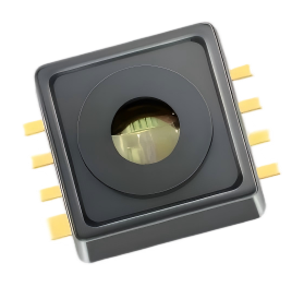
RP3311 is best evaluated as a compact MEMS absolute pressure sensor for MAP-style and other documented low-pressure air measurements. Its standard configuration uses a regulated 5 V supply, a 0.5-4.5 V analog output, and an SOP8 surface-mount package. It is not a universal drop-in replacement: the selected pressure range, transfer function, pressure port, temperature grade, and host ECU must match the application.
MAP describes the measurement point—manifold absolute pressure—not the sensor package alone. Confirm the pressure profile and air path before selecting a range.
This guide evaluates application fit only. It does not claim automotive-grade certification or vehicle-program production approval for RP3311.
The project requirements
A typical MAP replacement or second-source review starts with a practical requirement list. The goal is to match the complete intake-pressure measurement chain, not just a nominal pressure number.
- Absolute-pressure measurement at the intake or another defined air-pressure point
- A pressure window that covers normal vacuum, atmospheric pressure, and any validated transients
- A regulated 5 V sensor supply and an analog signal compatible with the ECU ADC
- Internal signal conditioning, sensor-level compensation, and production calibration
- Compact SMD construction, with the pressure path designed into the PCB or housing
- Operation across the required temperature profile, such as -40 °C to 120 °C, subject to grade confirmation
Several items in an early brief are alternatives rather than guaranteed features of every candidate. A 3.3 V-only controller may need a supply or interface redesign, and an analog sensor does not automatically provide the status reporting or diagnostics of a digital device.
How RP3311 matches the brief
The current RP3311 product listing provides the starting point below. The exact calibration, temperature grade, pressure interface, and qualification status must be confirmed for the proposed version.
- Pressure reference: absolute pressure, which is the reference used by MAP measurements.
- Standard ranges: 40-115 kPa and 50-400 kPa absolute. Select the range from measured manifold pressure, not from the package name.
- Range limits: the 40-115 kPa configuration may suit a documented low-pressure MAP point; the 50-400 kPa configuration is a broader absolute range and is not automatically a turbo-MAP replacement.
- Supply and output: 4.75-5.25 V supply with a 0.5-4.5 V analog output, so the ECU power rail and ADC input must be checked.
- Compensation and calibration: Reliava MEMS pressure sensors include an internal signal-conditioning IC, sensor-level compensation, and production calibration. The installed system still requires its own calibration and validation.
- Package: SOP8 surface mount. A PCB or housing change may be required if the existing sensor uses a different pressure interface or footprint.
- Environment: confirm total error, vibration, EMC, condensation, pressure pulses, and the selected temperature grade over the intended service life.
The important point is that a similar voltage span does not prove interchangeability. Engineers must still compare the pressure reference, calibrated endpoints, transfer function, pin assignment, pressure port, diagnostics, and temperature error.
What MAP pressure means in an engine system
MAP means manifold absolute pressure. The sensor measures the pressure inside the intake manifold against a vacuum reference. The ECU can combine this value with engine speed, intake temperature, throttle position, and other signals to estimate engine load and control fuel or ignition functions.
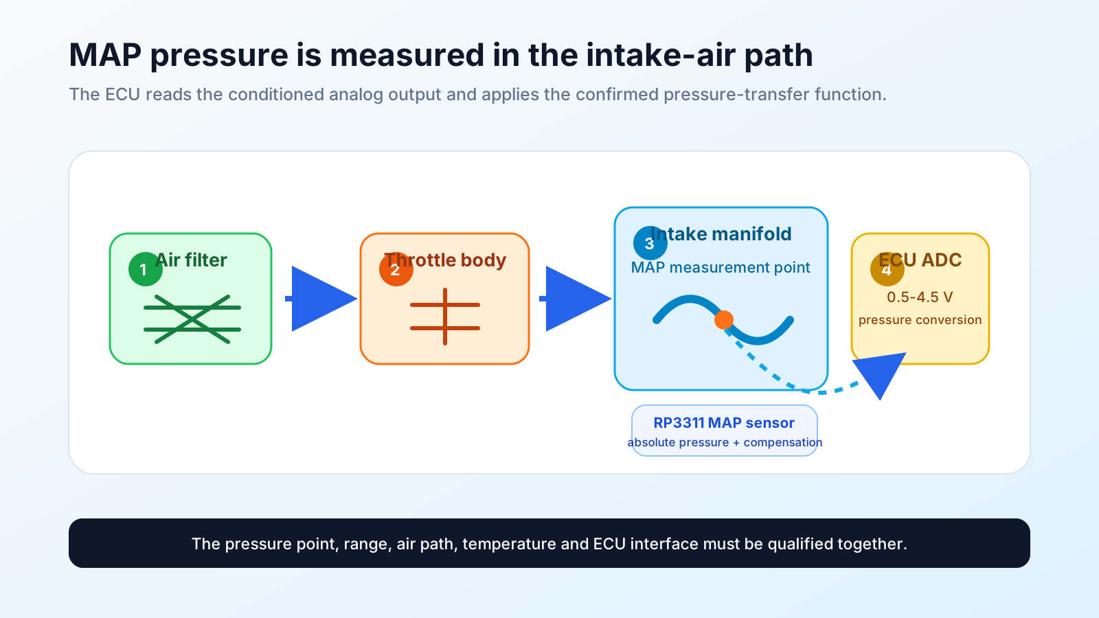
- Measurement point: the pressure port and hose or manifold must represent the intended intake location without leaks, blockage, or excessive dead volume.
- Air path: the sensor may encounter humidity, condensation, oil mist, dust, or cleaning residues; the pressure path and protective materials must be qualified together.
- Application boundary: MAP suitability does not automatically establish suitability for LPG or CNG fuel-gas lines. Fuel-gas use requires separate media, sealing, pressure, and system validation.
Why a compensated MEMS sensor can fit a MAP design
A MEMS sensing element converts diaphragm deflection into an electrical signal. In RP3311, the internal signal-conditioning IC converts the sensor signal into a usable analog voltage, while sensor-level compensation and production calibration improve repeatable behavior from device to device.
For an ECU that already reads analog channels, this architecture can simplify the pressure path: the ECU samples the voltage through an ADC and applies the approved pressure-transfer equation and diagnostic limits in software. It does not remove the need to verify output loading, filtering, fault thresholds, or firmware constants.
- Analog integration: check ADC range, reference, input impedance, protection, filtering, ground offset, and EMC.
- Digital feature gap: an analog output should not be assumed to provide CRC, internal temperature data, or the same diagnostic states as a digital sensor.
Selecting the pressure range
A MAP range must cover the lowest pressure that the control algorithm needs to measure accurately, the highest normal pressure, and credible transients. These values are different from proof pressure and burst pressure.
- Lowest accurate pressure: the lowest manifold pressure at which the ECU needs a defined measurement error.
- Maximum continuous pressure: the highest pressure present at the sensor port during normal operation.
- Transient or surge pressure: the highest credible pressure during throttle, valve, startup, or fault events.
- Proof and burst pressure: documented survival and failure limits that must never be inferred from the calibrated range.
The current product listing covers 40-115 kPa and 50-400 kPa absolute. If the MAP profile falls below the lower endpoint, the configuration is not a complete replacement without a confirmed alternative range. A wider span is not automatically better because it reduces useful output resolution across the normal operating band.
Before samples, provide the measured MAP profile, pressure spikes, output endpoints, accuracy target, and temperature range. Do not infer a 20-500 kPa or turbo-MAP calibration from the upper-range number alone.
Electrical integration: 5 V analog output
RP3311's standard 0.5-4.5 V output is intended for a controller ADC. The internal conditioning and production calibration provide a defined sensor-level output, while the OEM owns the final voltage-to-pressure conversion and system error budget.
- Power: provide a regulated 5 V rail within 4.75-5.25 V and verify startup and supply-transient behavior.
- Transfer function: record the output at the agreed pressure endpoints, slope, offset, tolerance, and any non-linearity before updating ECU constants.
- Fault strategy: define valid voltage windows and responses for open circuit, short to ground, short to supply, and sensor saturation.
- PLC or 4-20 mA input: a board-level voltage output is not a direct 4-20 mA field signal. Use a suitable interface or a complete pressure transmitter for that architecture.
Integrating the SOP8 package with the intake pressure path
SOP8 supports compact surface-mount assembly, but the package does not define the pressure connection by itself. A PCB or housing redesign may need a hose barb, manifold, gasket, sealed chamber, or adapter to route intake pressure to the sensing surface.
- Pressure path: prevent leaks, blockage, condensation, and excessive dead volume from changing response.
- Mechanical stress: control PCB bending, enclosure loading, adhesive shrinkage, and connector forces that can shift output.
- Assembly process: review reflow, cleaning, conformal coating, port sealing, and end-of-line pressure checks.
Media, temperature, and durability
MAP applications normally expose the pressure port to intake air or an air-fuel mixture, but real systems can also include humidity, condensation, oil mist, dust, and cleaning residues. Silicon or package compatibility alone cannot establish long-term reliability.
- Actual air-path composition and likely contaminants
- Direct or indirect exposure at the pressure port
- Pressure and temperature cycling over the intended service life
- Powered endurance, pressure pulses, leakage, and seal integrity
- Zero and span drift after exposure
- Compatibility of hoses, filters, O-rings, adhesives, gel, and enclosure materials
- Vibration, EMC, condensation, and applicable customer qualification requirements
The requested temperature range, such as -40 °C to 120 °C, must be treated as a qualification item rather than a survival checkbox. Confirm zero shift, sensitivity change, non-linearity, hysteresis, response, and total error for the selected configuration.
A room-temperature bench check is not production qualification. Test the sensor, PCB, pressure path, seals, enclosure, and ECU across the intended temperature, pressure, contamination, vibration, and life profile.
Accuracy and system-level error
RP3311 is compensated and calibrated during production, but a component specification is not the same as installed-system accuracy. Offset, span, non-linearity, hysteresis, repeatability, temperature effects, supply variation, output noise, mounting stress, pressure tubing, and contamination can all influence the final MAP reading.
- Normalize the number: convert ±%FS into pressure units using the defined calibration span.
- Read the definition: confirm which error sources are included in the accuracy specification and under which conditions.
- Check the full thermal profile: survival at a temperature endpoint is not the same as guaranteed measurement error across the range.
- Test the finished product: verify the sensor with representative PCB, pressure path, ADC, firmware, and enclosure.
A staged second-source qualification path
- Confirm the measurement point. Record the manifold location, normal pressure, transient pressure, air-path exposure, and local temperature.
- Freeze the RP3311 configuration. Agree on pressure reference, calibrated endpoints, transfer function, supply, output, accuracy, package, and pressure interface.
- Review the signal path. Confirm ADC limits, protection, filtering, fault thresholds, response time, and firmware changes.
- Build an evaluation batch. Compare the proposed sensor and the current design at the same pressure, temperature, supply, and output-load conditions.
- Run environmental and life testing. Include thermal cycling, pressure cycling, contamination, leakage, EMC, vibration, and drift checks as applicable.
- Complete system approval. Validate engine-control behavior, diagnostics, fail-safe response, traceability, and all required customer or application standards.
This process shows whether the expected cost or supply benefit remains attractive after PCB, tooling, firmware, signal-conditioning, and validation costs are included.
Is RP3311 a realistic MAP sensor candidate?
Yes, when the application needs an absolute-pressure sensor for a documented intake-air pressure point, can provide a regulated 5 V rail, can read a 0.5-4.5 V analog signal, and can accommodate an SOP8 board-level package. Its internal conditioning, compensation, and production calibration support a practical OEM evaluation, subject to the selected configuration and system qualification.
It is not the right choice when the required MAP profile extends below the confirmed lower calibration endpoint, a pin-compatible footprint is mandatory, 3.3 V-only operation is required, native digital diagnostics are essential, or a complete 4-20 mA field transmitter is needed. Those requirements call for another configuration or a broader redesign.
For an engineering recommendation, send Reliava the measurement location, pressure profile, surge pressure, air-path materials, temperature profile, schematic, pressure-port drawing, output and supply constraints, annual quantity, and required qualification standard.
Frequently asked questions
Is RP3311 a MAP sensor?
RP3311 is an absolute-pressure MEMS sensor that can be evaluated for MAP-style intake pressure measurement when the selected range, pressure port, output transfer function, temperature grade, and ECU interface match the application. The product page does not make every MAP range or vehicle-program qualification automatic.
Does RP3311 connect directly to an ECU?
It can be connected to an ECU analog input when the ECU accepts the 0.5-4.5 V signal and the power, protection, filtering, grounding, and fault thresholds are designed accordingly. Firmware must use the confirmed pressure-transfer function.
Can RP3311 connect directly to a PLC?
Usually not. RP3311 provides a board-level analog voltage, while many PLC installations expect 4-20 mA, 0-10 V, or a supported industrial bus. Use a suitable interface or select a complete pressure transmitter.
Does the 50-400 kPa version automatically work for turbo MAP?
No. The range may cover a pressure value, but turbo-MAP suitability also depends on the calibrated endpoints, pressure pulses, response, temperature error, pressure port, and system qualification. Confirm the complete pressure profile before selecting it.
Can RP3311 be used in an LPG or CNG fuel-gas line?
Not by default. MAP positioning does not establish fuel-gas media compatibility. Any LPG or CNG use requires separate confirmation of gas composition, materials, seals, pressure limits, contamination, temperature, and system approvals.
What information is needed before samples?
Provide the intake measurement point, pressure profile, normal and maximum pressure, transient pressure, temperature profile, pressure-port drawing, supply and output constraints, accuracy target, annual volume, and required qualification standard.
Related Reliava resources and product information
Review the current RP3311 MEMS pressure sensor listing, then use the pressure sensor selection guide and the gauge, absolute, and differential pressure guide to confirm the measurement reference. For a field-ready 4-20 mA installation, review the RT4013 pressure transmitter instead.
For application review, contact Reliava engineering with the pressure, air-path, interface, and qualification details listed above.