
What Is the Difference Between Analog and I²C Output?
An analog pressure sensor produces a voltage that changes with pressure. The host measures that voltage with an analog-to-digital converter and applies the product's transfer function.
An I²C pressure sensor communicates digital data using a serial data line and serial clock line. I²C defines the bus and transfer method; the sensor datasheet defines the address, commands, data format, conversion timing, and pressure calculation.
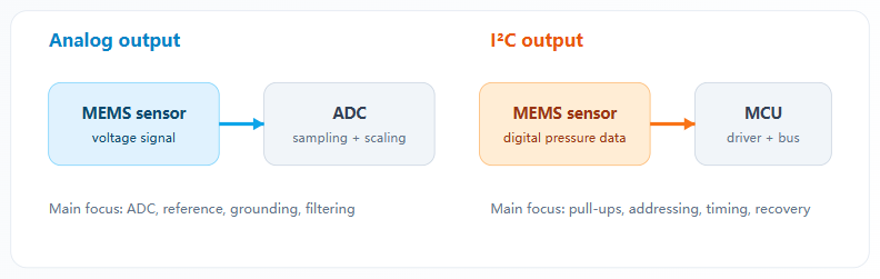
How Does an Analog MEMS Pressure Sensor Fit Into the System?
For a linear voltage-output sensor, the controller converts voltage into pressure using the documented endpoints. A generic relationship is:
Pressure = Pmin + (Vout - Vmin) / (Vmax - Vmin) × (Pmax - Pmin)
This is only an illustration. The selected sensor's datasheet controls the actual transfer function, clipping limits, tolerance, and supply conditions.
Analog output is easy to observe during development: an engineer can probe the signal and check whether it responds to pressure. It can also fit an existing design without adding a digital protocol.
The final result depends on the complete analog chain. ADC resolution, voltage reference, input range, source impedance, grounding, supply noise, PCB routing, and filtering can all affect the measurement. Do not assume the output is ratiometric unless the datasheet explicitly says so.
How Does an I²C MEMS Pressure Sensor Fit Into the System?
I²C uses serial data (SDA) and serial clock (SCL) lines with pull-up resistors. A controller communicates with addressed devices on the bus. The timing diagram below shows the START and STOP conditions, address and R/W bits, acknowledge (ACK) cycles, and data bytes.
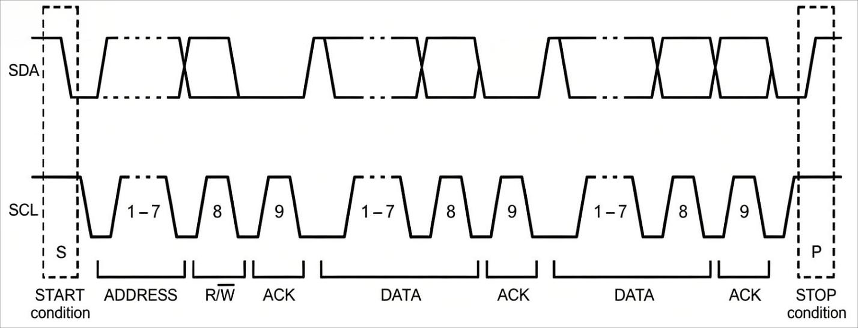
Depending on the sensor, the host may need to start a conversion, wait for a specified time, read bytes, check status bits, assemble a raw value, and apply a conversion equation. The exact sequence is product-specific.
Digital output avoids carrying the pressure value to the host as an analog voltage, but it does not eliminate integration risk. Incorrect pull-ups, excessive capacitance, voltage mismatch, address conflicts, timing errors, or long wiring can make the bus unreliable.
Seven Questions That Decide the Interface
1. What interface does the controller already support?
If a proven ADC channel is available and firmware resources are limited, analog may be faster. If the MCU already uses I²C and has software resources for another device, digital integration may reduce analog circuit work.
2. How far is the sensor from the controller?
Both interfaces are normally used over short connections inside equipment. I²C should not be treated as a long-distance industrial field bus. Its practical limit depends on bus capacitance, pull-ups, clock timing, voltage levels, and noise—not a universal cable length.
3. What noise and grounding conditions exist?
Analog signals require careful ground, return-current, filtering, routing, and ADC-reference design. I²C avoids an external analog measurement path, but its digital thresholds and edges still require sound PCB design and interference control.
4. How much firmware can the project support?
Analog needs sampling, filtering, scaling, and limit checks. I²C needs initialization, address and command handling, timing, byte parsing, timeout logic, and recovery from communication faults. Compare total engineering and validation effort.
5. Are multiple sensors required?
Several I²C devices can share SDA and SCL only if their addresses are compatible and total bus loading stays within specification. Identical sensors may have fixed or limited address options. Analog sensors usually use separate ADC channels or a multiplexer.
6. What update rate is needed?
Check sensing response, conversion time, output bandwidth, bus speed, host sampling, and control-loop requirements. A fast communication interface does not make the pressure-sensing element respond faster.
7. How will the system detect faults?
For analog, define valid voltage limits and behavior for open, short, and out-of-range conditions. For I²C, define timeouts, status handling, invalid data behavior, and bus recovery. Test power interruption and connector faults during validation.
Reliava Analog and I²C MEMS Options
Reliava's current product pages list the following interface options for the two relevant MEMS families:
- RP301x: gauge pressure; ±10 kPa, ±40 kPa, and ±100 kPa ranges; 0.2–2.7 V, 0.5–4.5 V, or I²C output; SOP6 package.
- RP321x: absolute pressure; 0–100 kPa and 0–700 kPa ranges; 0.2–2.7 V, 0.5–4.5 V, or I²C output; LGA3 package.
Both series list ±1% FS accuracy in the Reliava catalog. Before design-in, confirm the exact ordering code, transfer function, supply, pinout, I²C protocol, temperature range, media compatibility, and mechanical requirements in the full datasheet.
For background on the sensing element, see our MEMS pressure sensors explainer. For pressure reference selection, see our gauge, absolute, and differential pressure guide.
Quick Selection Rule
Choose analog when the design already has a suitable ADC, the connection is short and controlled, and directly probing the signal is useful.
Choose I²C when the host is MCU-based, digital data fits the architecture, the bus is electrically suitable, and the project can support protocol firmware and error handling.
FAQ
Is I²C more accurate than analog output?
Not automatically. I²C avoids error in an external analog transmission and ADC stage, but total accuracy still depends on the sensing element, calibration, temperature, internal conversion, and product specification.
Does an I²C pressure sensor need an ADC?
The host normally receives digital pressure data and does not need to digitize an analog sensor output. The sensor contains the conversion and signal-conditioning functions required by its design.
Can I²C be used over a long cable?
I²C is primarily intended for short connections within a board or piece of equipment. Longer wiring increases capacitance and noise exposure. Validate the actual design against the sensor and I²C electrical requirements.
Can several identical I²C pressure sensors share one bus?
Only if their addresses can be made unique or the system uses suitable bus multiplexing. Confirm the sensor's address options before finalizing the architecture.
Conclusion
Analog and I²C MEMS pressure sensors solve different integration problems. Analog provides a direct voltage signal and fits established analog designs. I²C provides digitally formatted data and can simplify the host measurement chain, but it requires correct bus hardware and robust firmware.
To select an RP301x or RP321x variant, send Reliava your pressure reference, range, medium, supply, interface, host controller, update rate, package constraints, and annual volume. Contact the Reliava engineering team for full specifications and sample recommendations.