
Choose the Narrowest Range That Covers the Full Pressure Envelope
Choose the narrowest calibrated MEMS pressure sensor range that covers every pressure the system must measure accurately. Then confirm that transients, reverse pressure, and foreseeable faults stay within the sensor's documented overload limits.
For low-pressure applications, the correct choice is rarely based on the normal operating point alone. Compare the minimum and maximum measured pressure, startup and shutdown peaks, pressure direction, required error in pascals, temperature, media, tubing, package, and electrical interface.
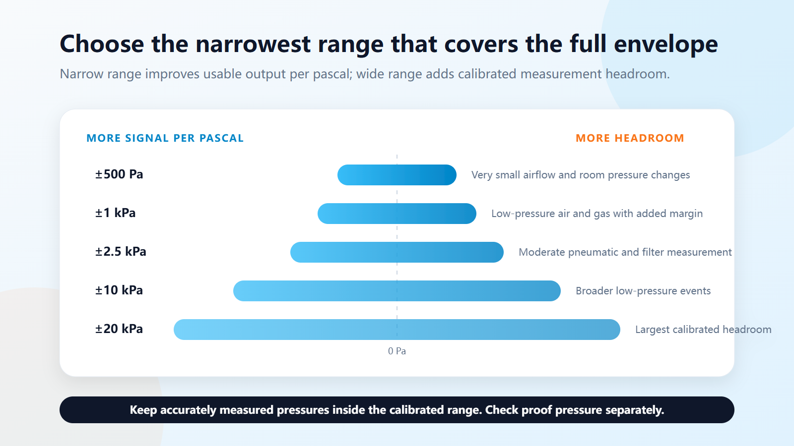
Quick Low-Pressure Range Selection Guide
- ±500 Pa: Best for very small bidirectional pressure changes such as sensitive airflow control, room-pressure monitoring, and low differential pressure across clean filters. Confirm that real transients do not exceed ±500 Pa.
- ±1 kPa: Adds headroom for low-pressure air and gas systems while retaining useful sensitivity around zero. Specify the endpoints because “1 kPa sensor” could also mean a unidirectional 0 to 1 kPa device.
- ±2.5 kPa: Fits moderate low-pressure airflow, pneumatic, filter, and respiratory measurements whose accurately measured envelope extends beyond ±1 kPa.
- ±10 kPa: Provides substantially more operating headroom for broader pneumatic and differential pressure events. Verify that the complete error and noise budget still resolves the smallest required change.
- ±20 kPa: Covers larger bidirectional pressure excursions while keeping the compact MEMS differential architecture. Use it when the validated measurement envelope exceeds ±10 kPa, not merely as a precaution.
- A requested 5 kPa range: First clarify whether the request means 0 to 5 kPa, ±5 kPa, gauge, or differential. Compare a customized 5 kPa option with standard ±10 kPa performance and availability.
A range recommendation is a starting point, not a substitute for the selected sensor's full datasheet and application testing.
What Does MEMS Pressure Sensor Range Mean?
The measurement range is the pressure interval over which the manufacturer specifies the sensor's output and performance. It has a lower range value and an upper range value. The span is the difference between those endpoints.
- 0 to 1 kPa is a unidirectional range with a total span of 1 kPa.
- -0.5 to +0.5 kPa is a bidirectional range with a total span of 1 kPa.
- -20 to +20 kPa is a bidirectional range with a total span of 40 kPa.
Before converting an accuracy percentage into pascals, check how the manufacturer defines full scale, span, and %FS. These terms are not applied identically in every datasheet.
Step 1: Choose the Correct Pressure Reference
Range selection cannot be separated from pressure reference. A numerically correct kPa value can still produce the wrong system behavior if the sensor measures against the wrong reference.
- Differential pressure: Measures the pressure difference between two ports, ΔP = P1 - P2. Common uses include airflow, filter condition, room or duct pressure, and small pneumatic changes.
- Gauge pressure: Measures pressure relative to local atmospheric pressure. It is suitable when the system needs to know how far pressure is above or below ambient air.
- Absolute pressure: Measures pressure relative to a sealed vacuum reference. It is normally selected for barometric, vacuum, or altitude-related measurements where atmospheric variation must remain part of the reading.
For a deeper comparison, see Gauge vs Absolute vs Differential Pressure Sensors.
Step 2: Build the Complete Pressure Envelope
Do not select a sensor from one nominal pressure. Build an envelope from measurements, simulations, component tolerances, control modes, and worst-case system requirements.
- Normal operating band: Where the system spends most of its time.
- Minimum accurately measured pressure: The lowest value that must meet the application error requirement.
- Maximum accurately measured pressure: The highest value that must remain inside the calibrated range.
- Expected transient pressure: Startup, shutdown, fan changes, valve switching, pulsation, and restricted tubing can create short peaks.
- Foreseeable fault pressure: Consider blocked tubes, reversed ports, pump faults, disconnections, and misuse.
- Reverse pressure: Determine whether pressure can cross zero or be applied to the nominal low-pressure port.
Decide whether each event must be measured accurately or merely survived. Accurate events belong inside the calibrated measurement range. Survival-only events may fall outside that range only when the datasheet explicitly permits them.
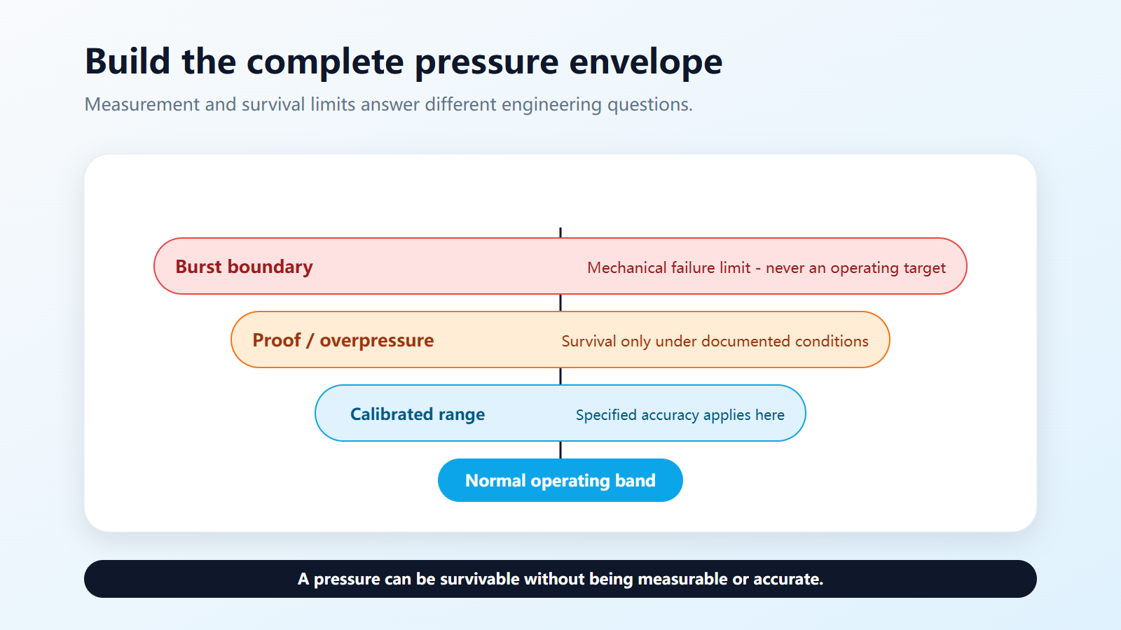
Step 3: Separate Measurement Range, Proof Pressure, and Burst Pressure
- Measurement range: The calibrated interval over which the stated accuracy and other performance limits apply under the specified conditions.
- Overpressure or proof pressure: A pressure the sensor can withstand under defined conditions without permanent damage or performance change. Published accuracy normally does not apply outside the measurement range.
- Burst pressure: A mechanical failure or containment limit. It is not an operating target and does not imply useful measurement.
Repeated spikes can cause zero shift or long-term damage even when the normal pressure is well inside range. Verify pressure direction, duration, number of cycles, common-mode pressure, temperature, and port conditions in the full datasheet.
Step 4: Calculate the Effect of Range on Usable Measurement
Suppose two sensors use the same number of output counts across their calibrated spans. Sensor A covers -0.5 to +0.5 kPa, a 1 kPa total span. Sensor B covers -10 to +10 kPa, a 20 kPa total span.
A 100 Pa change occupies 10% of Sensor A's span but only 0.5% of Sensor B's span. The narrower sensor therefore assigns a larger share of its available output to that change.
This does not prove that Sensor A delivers twenty times better real-world resolution or accuracy. Actual performance also depends on noise, total error, temperature effects, repeatability, output quantization, filtering, sampling, power stability, tubing, and mounting stress.
If accuracy is stated as a percentage of full scale, use the manufacturer's definition and test conditions. Do not infer system accuracy from digital bit depth alone.
When to Choose Each Low-Pressure MEMS Range
When to Choose a ±500 Pa Pressure Sensor
A ±500 Pa sensor covers -500 to +500 Pa and is useful when small bidirectional changes around zero must be detected. Typical applications include sensitive HVAC airflow control, air-filter pressure-drop monitoring, room-pressure control, and low-flow gas systems.
Choose this range only after confirming that startup peaks, purge cycles, tubing errors, and reversed-port events stay within the documented limits. Reliava's RP3112D family includes a ±0.5 kPa option for differential measurement.
When to Choose a ±1 kPa Pressure Sensor
Compared with ±500 Pa, a ±1 kPa range doubles the pressure headroom in each direction. It can be a better choice when the normal signal is small but validated system events can exceed 500 Pa.
State the endpoints explicitly in specifications and purchase requests. A “1 kPa pressure sensor” may mean 0 to 1 kPa or -1 to +1 kPa, and those devices are not interchangeable.
When to Choose a ±2.5 kPa Pressure Sensor
A ±2.5 kPa sensor provides additional range for systems with larger air or gas pressure variation. It may suit a design whose normal pressure stays below 1 kPa but whose calibration modes or validated operating states extend beyond that value.
Before selecting it over ±1 kPa, calculate the smallest pressure change the complete system must distinguish and confirm the result at the critical operating points.
What If the Design Requires a 5 kPa Range?
Clarify whether 5 kPa means 0 to 5 kPa, -5 to +5 kPa, gauge, absolute, or differential. Then compare the exact pressure envelope with the manufacturer's standard ranges.
If ±5 kPa is not a standard option, compare a customized range with a standard ±10 kPa version using the complete error, noise, availability, qualification, and annual-volume requirements.
When to Choose a ±10 kPa Pressure Sensor
A ±10 kPa sensor provides greater headroom for larger low-pressure events and broader pneumatic measurement. It is appropriate when accurately measured pressures exceed ±2.5 kPa but remain inside ±10 kPa with the required margin.
Do not choose ±10 kPa solely because it feels safer. If the system must distinguish changes of only tens of pascals, compare the actual error and noise budget with narrower ranges.
When to Choose a ±20 kPa Pressure Sensor
A ±20 kPa sensor is appropriate when the validated measurement envelope includes bidirectional pressures above 10 kPa, or when a broader calibrated range is needed for multiple operating modes. Reliava now offers an RP3112D ±20 kPa option alongside the ±0.5, ±1, ±2.5, and ±10 kPa ranges.
Because ±20 kPa has a 40 kPa total span, confirm that its absolute error, noise, update rate, and transfer function still support the smallest pressure change that matters. Do not use proof pressure as a substitute for a calibrated ±20 kPa range.
Step 5: Check Temperature, Media, and Mechanical Integration
The right numerical range is not automatically the right sensor. Review the complete electrical, environmental, and mechanical design.
- Compensated and operating temperature ranges
- Clean dry air, compatible gas, liquid, or other media
- Condensation, humidity, dust, and contamination exposure
- Common-mode or line pressure on both differential ports
- Port direction, size, tube retention, leaks, and restrictions
- PCB footprint, package height, mounting stress, and reflow profile
- Supply voltage, power consumption, I²C levels, address, and timing
- Calibration, traceability, repeatability, and long-term stability
For low-pressure measurement, tubing and installation are part of the system. Long or restricted tubes change response time. Leaks, sharp bends, condensate, and poorly positioned pressure taps can introduce errors that a more accurate MEMS element cannot correct.
Can RP3112D Be Evaluated as an SM9541 Alternative?
RP3112D can be evaluated as an SM9541 alternative candidate for overlapping low-pressure differential applications, but it should not be described as a verified drop-in or pin-to-pin replacement without a complete engineering comparison.
The public SM9541 Series product sheet describes I²C, SOIC-16 gauge and differential configurations with approximately ±1, ±2, ±4, and ±10 kPa differential ranges. RP3112D covers ±0.5, ±1, ±2.5, ±10, and the newly added ±20 kPa range. Similar package names, pressure ranges, or headline accuracy do not establish interchangeability.
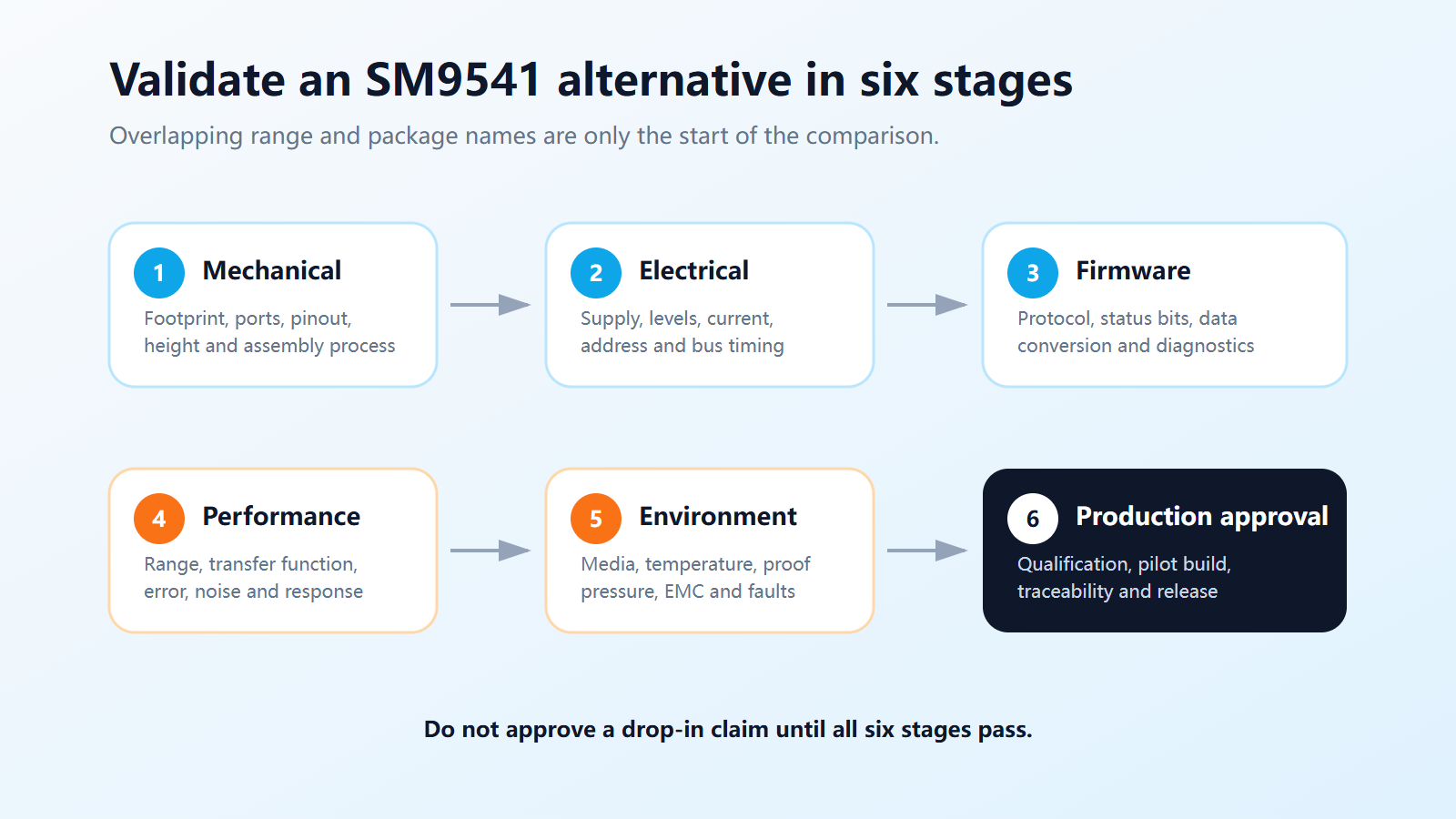
- Compare footprint, pinout, pressure ports, package height, and assembly process.
- Compare supply, I²C address, protocol, timing, status bits, and data conversion.
- Compare range endpoints, transfer function, accuracy definitions, noise, and temperature performance.
- Compare media, common-mode pressure, proof pressure, burst pressure, and fault behavior.
- Complete bench, EMC, environmental, qualification, and pilot-production validation.
Worked Selection Examples
Example 1: HVAC Filter Monitoring

Assume the clean-filter pressure drop is 80 Pa, the dirty-filter alarm is 300 Pa, reverse flow can reach -120 Pa, and startup peaks reach +420 Pa. If all values must be measured, a unidirectional 0 to 500 Pa device is unsuitable because it cannot report reverse pressure. A bidirectional ±500 Pa sensor may cover the envelope if its overload capacity and worst-case margin are adequate.
If testing reveals legitimate peaks above 500 Pa, compare ±1 kPa. The final decision should use the actual error and noise of both ranges near 80 Pa and 300 Pa.
Example 2: Respiratory or Gas-Flow Equipment
Suppose normal operation stays within ±800 Pa, a calibration mode reaches ±1.8 kPa, and a blocked tube produces a larger survival-only pressure. A ±1 kPa device cannot measure the calibration mode, while ±2.5 kPa may cover the required measurement envelope. The fault must remain below the documented proof or overpressure limit.
Medical and safety-related equipment requires application-specific risk management, validation, and regulatory review. A component's nominal range alone does not establish suitability.
Example 3: A Request for a 5 kPa Sensor
Suppose an OEM expects -3.5 to +4.2 kPa and requests a “5 kPa pressure sensor.” Rewrite the requirement as a differential range covering at least -3.5 to +4.2 kPa, together with transient, overload, error, temperature, media, output, and package requirements.
Then compare a customized range with a standard ±10 kPa version. The decision depends on the complete measurement and commercial requirements, not the shorthand “5 kPa.”
MEMS Pressure Sensor Range Selection Checklist
- Pressure reference: differential, gauge, or absolute
- Lower and upper accurately measured pressure endpoints
- Normal operating band and smallest detectable change
- Transient pressure, duration, frequency, and number of cycles
- Fault, reverse-pressure, common-mode, and line-pressure conditions
- Required absolute error in pascals, noise, and response time
- Media, wetted materials, humidity, and condensation requirements
- Ambient and media temperatures
- Analog or digital interface, supply, host controller, and update rate
- Package, footprint, pressure ports, tubing, and mounting orientation
- Calibration, traceability, qualification, and regulatory requirements
- Prototype quantity, expected annual volume, and customization needs
Frequently Asked Questions
What Is an Ultra-Low-Pressure Sensor?
An ultra-low-pressure sensor is designed to measure small gauge or differential pressures, commonly in air and compatible gases. There is no universal boundary for the term, so selection should be based on the required endpoints, error, noise, overload, and application conditions.
Should I Choose ±500 Pa or ±1 kPa?
Choose ±500 Pa when every accurately measured pressure fits between -500 and +500 Pa with adequate margin and documented overload capacity. Choose ±1 kPa when real operating events exceed those endpoints, then confirm it still resolves the smallest required change.
Is ±2.5 kPa More Accurate Than ±10 kPa?
Not automatically. A narrower range assigns more of the output span to each pascal, but real accuracy depends on the sensor's error specification, noise, temperature compensation, repeatability, and installation.
Can a Differential Sensor Measure Negative Pressure?
A bidirectional differential sensor can report negative ΔP when the pressure on the nominal low side exceeds the pressure on the high side. Confirm the allowed range and port direction in the datasheet.
When Is ±20 kPa Better Than ±10 kPa?
Choose ±20 kPa when pressures above ±10 kPa must be measured accurately or the complete validated envelope requires the wider calibrated range. If those larger events only need to be survived, compare them with the ±10 kPa device's documented proof pressure before increasing the measurement range.
Is RP3112D a Drop-In SM9541 Replacement?
No drop-in compatibility should be assumed from public summary specifications. Compare and validate the footprint, ports, pinout, supply, I²C behavior, transfer function, pressure and temperature performance, media, overload ratings, and qualification requirements.
Conclusion
The correct low-pressure MEMS sensor range is the narrowest calibrated interval that covers the complete accurately measured pressure envelope while meeting overload, error, resolution, temperature, media, and integration requirements. ±500 Pa is suitable for very small airflow changes, while ±1, ±2.5, ±10, and ±20 kPa provide progressively more measurement headroom.
Reliava's RP3112D differential MEMS pressure sensor is available in ±0.5, ±1, ±2.5, ±10, and ±20 kPa ranges. Send your pressure envelope, medium, temperature, interface, package, error requirement, and annual volume to the Reliava engineering team for a standard product, customized range, or SM9541 alternative evaluation.